Adding A Gong Ringer to a Payphone
While the 2110V board we installed in our first payphone has a handy ringer module to alert people nearby of incoming calls, it does not sound anywhere near as good as a traditional gong-ringer that you may have encountered in rotary or early touch-tone telephones.
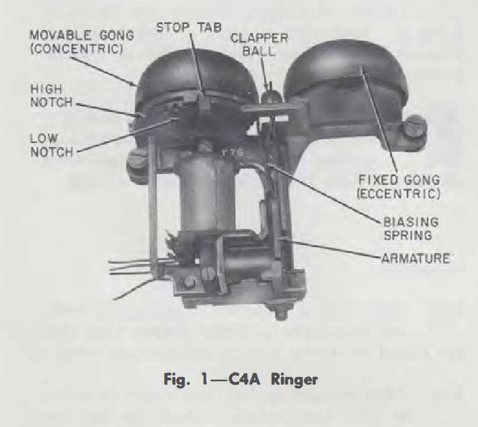
Telephone gong ringers are readily available for purchase on the second-hand market, and you can acquire one for about $15. We were able to pick up an inexpensive C4A ringer, which would typically be found in an older Western Electric 500 desk phone. C4A ringers typically come in two varieties: two-wire and four-wire. For all intents and purposes, these ringers behave identically, but the difference (as you can probably guess by the name) is how these ringers are wired up.
Your classic phone line consists of two conductors: tip (green) and ring (red). When a call comes in, 90-volt 20-hertz alternating current comes down the phone line to trigger a ring. The phone line is also using 48-volt direct current to determine if the phone is on/off hook, so a capacitor is needed in series with a ringer and the phone line which will block DC and allow AC to pass through to the ringer. Without the capacitor, the DC would loop on the line indicating an off-hook condition, so the phone would never ring.
Our C4A is a two-wire variety, so we can simply connect a capacitor to one of the two leads, and then connect the remaining lead and the unconnected leg of the capacitor to tip or ring respectively (polarity of the phone line does not matter) to complete the circuit. Four-wire C4A ringers utilize two leads to connect to the capacitor only, and leave the remaining two leads to connect to tip/ring.
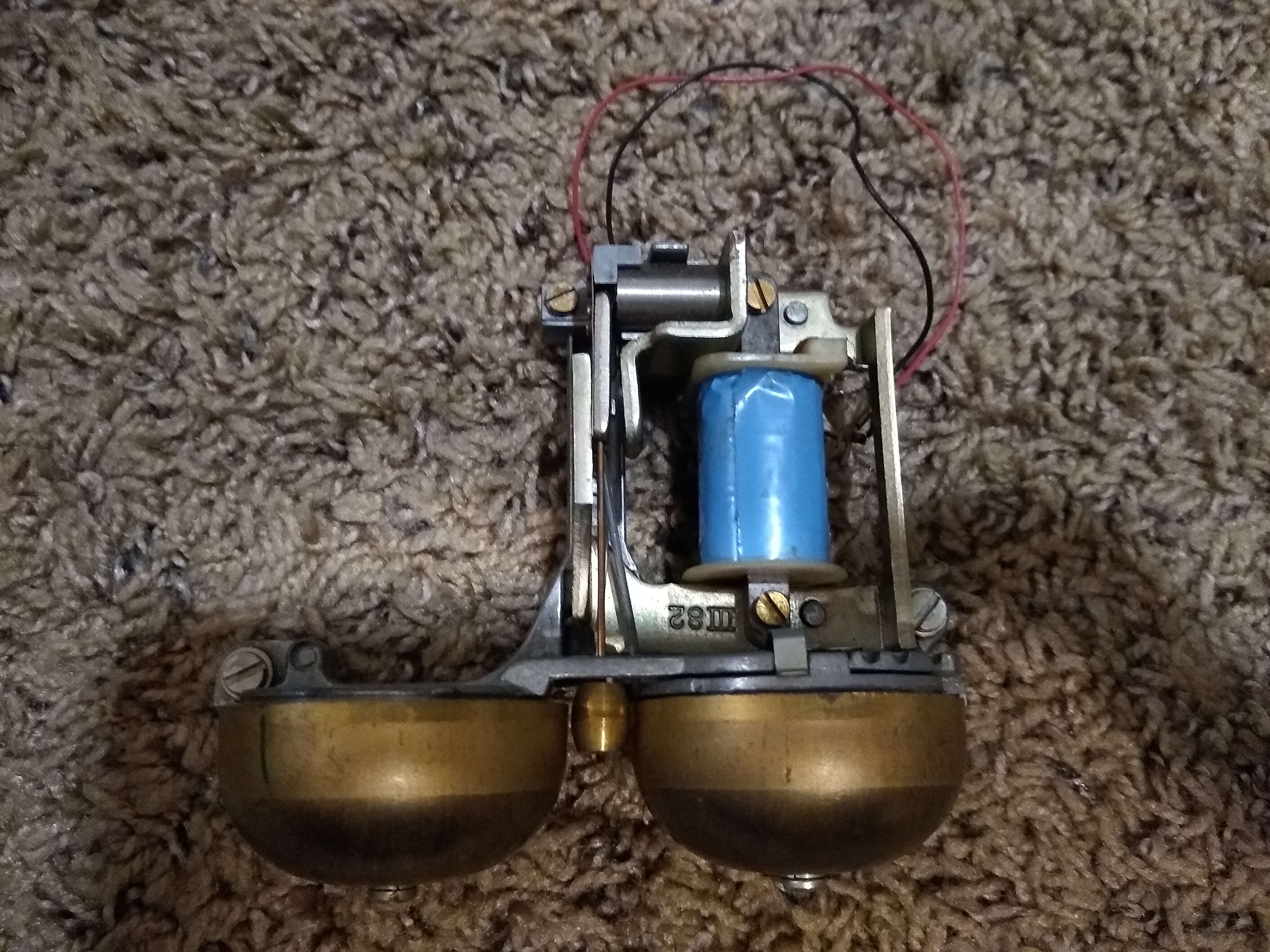
In a typical phone using one of these ringers, the capacitor would be contained within the telephone’s network: a potted metal box with exposed screw-terminals that contains the circuitry to make the telephone work. We happened to have a partially broken network out of a demonstration phone we were using, but the internal capacitor still worked fine!
We can connect one lead of our ringer to terminal A on the network and one conductor from the phone line to terminal K. The remaining ringer lead can then be connected to the remaining telephone line conductor and now our ringer will ring when we receive an incoming call!
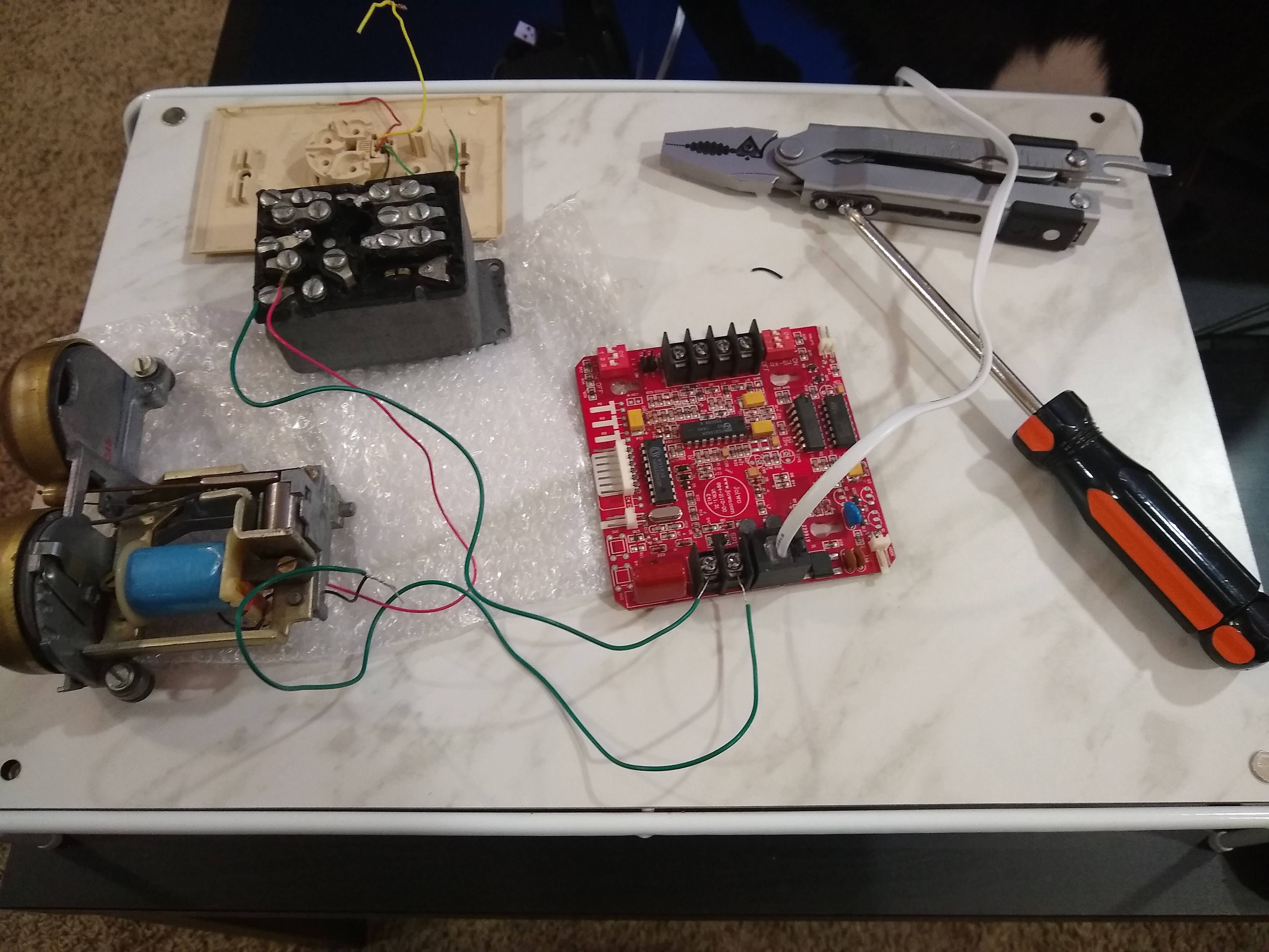
This is a completely functional and reasonable setup, but to reduce the physical footprint of these components, we can replace the network with a modern capacitor that will accomplish the same task. Based on some Internet searches, a proper capacitor for our ringer would be rated at 0.47 uF, and we want to make sure that it can handle over 100+ volts as there can be some variance in ringing power. We found a properly spec’d replacement capacitor made by Würth Elektronik rated at 310 volts for only 64 cents at the time of writing! Note that this is a film capacitor, which aside from using a different dielectric than ceramic/electrolytic capacitors, tends to perform better for audio applications. The cost difference between a film capacitor and a ceramic one seems to be minimal so it makes sense to purchase it (though you would most likely be fine using a ceramic capacitor of the same value).
We can connect our new capacitor in series with the ringer and phone line just as we did with our network and hear ringing when a call comes in!
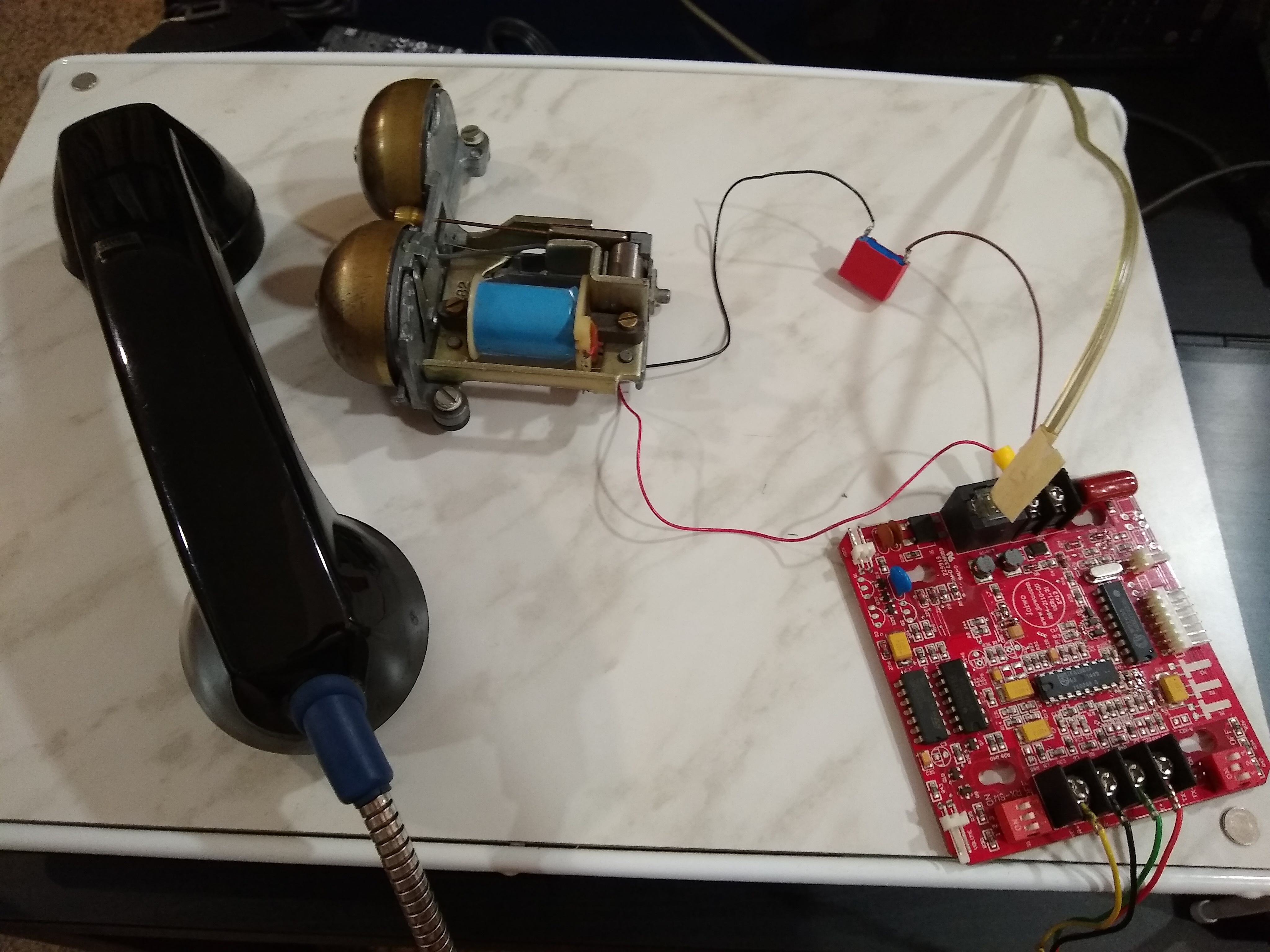
At this point, you may have picked up on the fact that we essentially created an “external ringer” meaning that this ringer can physically exist far away from a phone and operate just fine by itself. Provided your phone has a ringer already, you could even have both ring when a call comes in! Technically, we will be putting this ringer in parallel with our 2110V board in the payphone, and the easiest way to do that is to wire everything together via the two phone line screw terminals on the board. These two terminals are bridged with the proper pins in the RJ-11 socket that we are currently using to connect our phone to our ATA, so these terminals will give us the connection to the telephone line that we need.
For a quick installation, after the components are all wired together we have zip-tied the ringer to the handset cord strain-relief bracket in the upper housing. We also disconnected the electronic ringer daughter board from the 2110V.
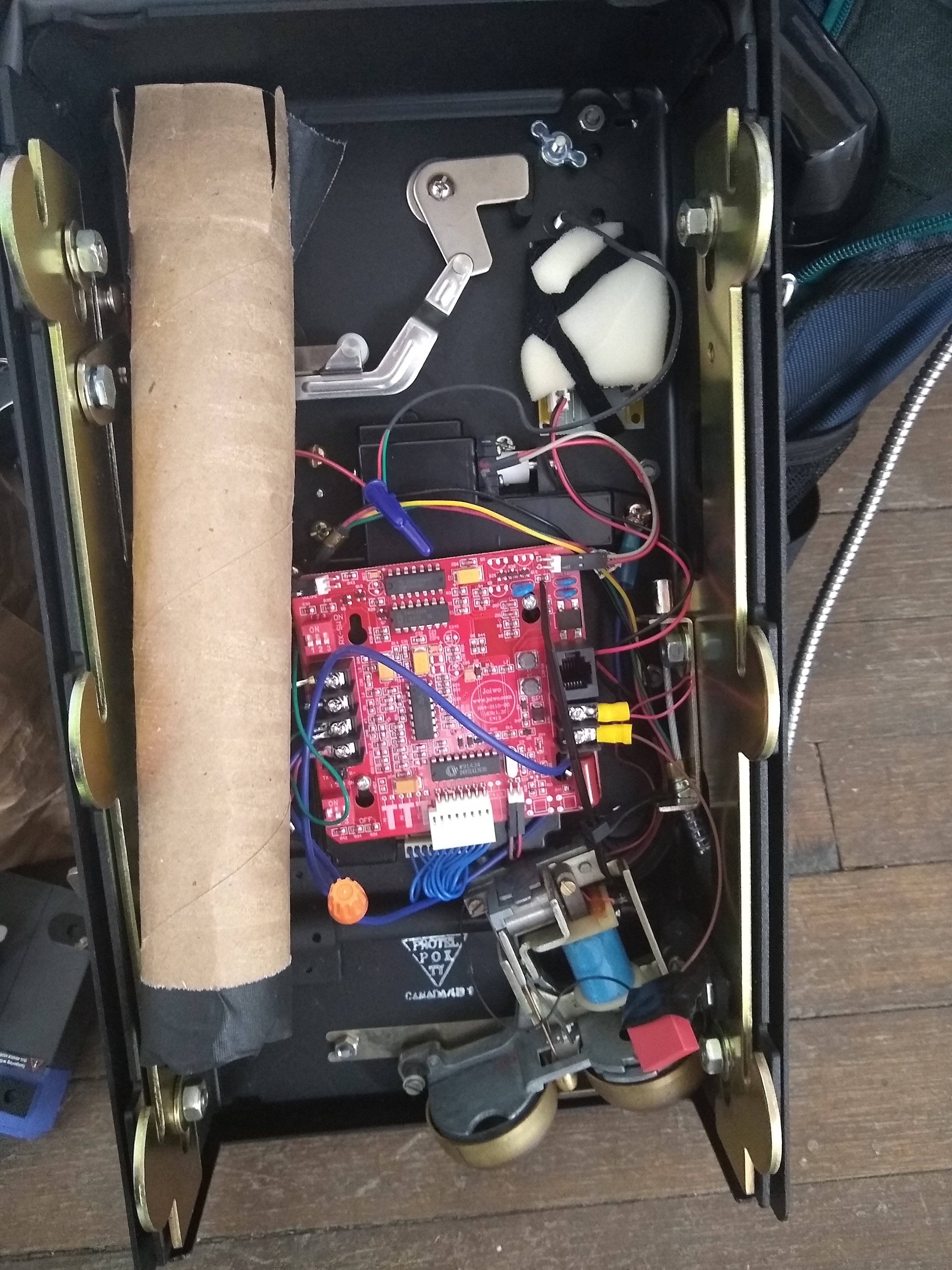
Now the phone has a mechanical ring when called.
One additional thing that was needed for the ringer to work in this setup was to set the ringer power to high in our ATA settings. This can be done by logging into the Grandstream ATA, navigating to FXS Port from the top navigation, toggling Enable High Ring Power to Yes and then pressing the Apply button. This increases the REN (Ringer Equivalency Number) which is occasionally needed to power gong ringers or multiple phones on one line as more modern phones require less power to ring.

Something else to note that we will revisit, certain ringers have what is known as a bias spring that can be set at multiple positions to adjust how the clapper can contact the bell. Our spring may be set incorrectly which could be the reason we need higher ringer power.