Use A Protel Keypad with the 2110V Coinless Board
A little while ago we noticed that the Bell Coinless Keypad that we use in conjunction with the 2110V coinless boards is no longer for sale from any retailer. This left us in a bit of a dilemma as we weren’t sure how we would be able to continue using these boards if we couldn’t find a compatible keypad. Luckily, we did still have one Coinless keypad around and a few Protel keypads that went unused when we decided to remove the Protel hardware from our payphone build.
From my experience building a blue box, I knew that many keypads had the keys wired in a matrix such that there is one wire for each column (three in total) and one wire for each row (four in total). When pressing a key, a column wire and a row wire are shorted together and whatever is hooked up to the keypad can identify this as a specific key-press.
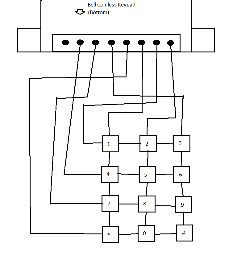
Since I still had a Coinless keypad, I took to determining this mapping by “buzzing out” the eight pins on its connector with a simple multimeter set in continuity mode. Using continuity mode, a multimeter will emit a beeping sound whenever the two leads contact one another. Therefore, if I connect these leads to different pins coming out of any given keypad and press the proper button, the multimeter should beep letting me know these two pins correspond to the row/column combination for this key.

This is done randomly at first. I simply connected each probe to a different pin on the back of the keypad and pressed buttons until I heard a beep. If I didn’t hear any beeping after trying all the buttons, I would move one or more leads to different pins. Remember, you could be connected to two column pins or two row pins and in that case never have a connection (this keypad also has eight pins when we know that we only need seven for the keys, so one will be unused). When I was finally able to hear a beep, I kept one lead on the same pin and moved the other lead to a different pin. We know that one of those pins is a column and one is a row, but not which is which, so we can leave one there and try different keys in the same row/column as our successful key until we see a pattern and are able to determine if that pin belongs to a row or a column. Once I could determine a pin corresponded to a row or column, I marked it down and continued to test until all rows and columns were known.
The Protel keypad has a DB-25 connector, so there were a lot more possible pins here that needed to be checked in the same manner.
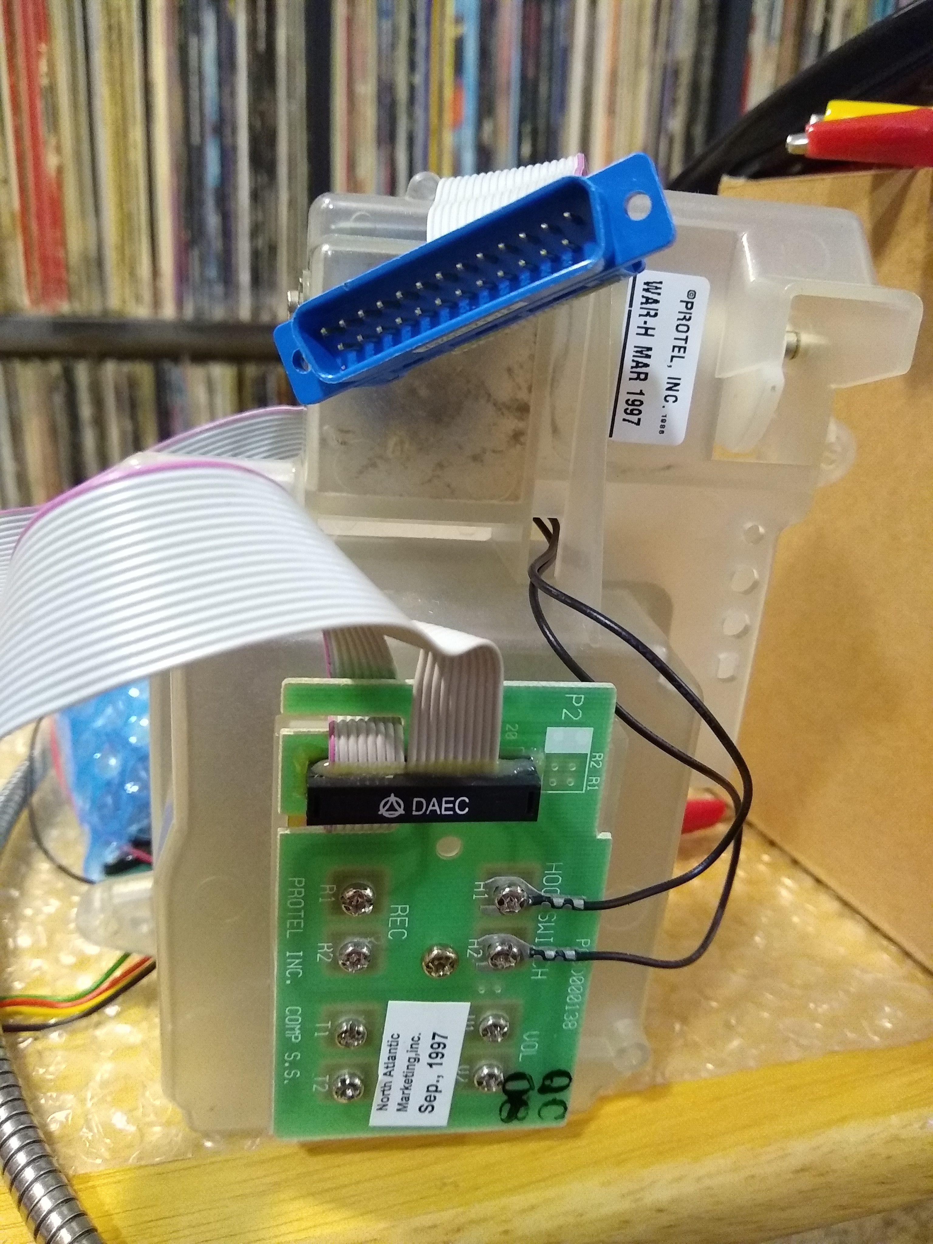
Nevertheless, by brute force I was able to test each pin and create a diagram for it as well.
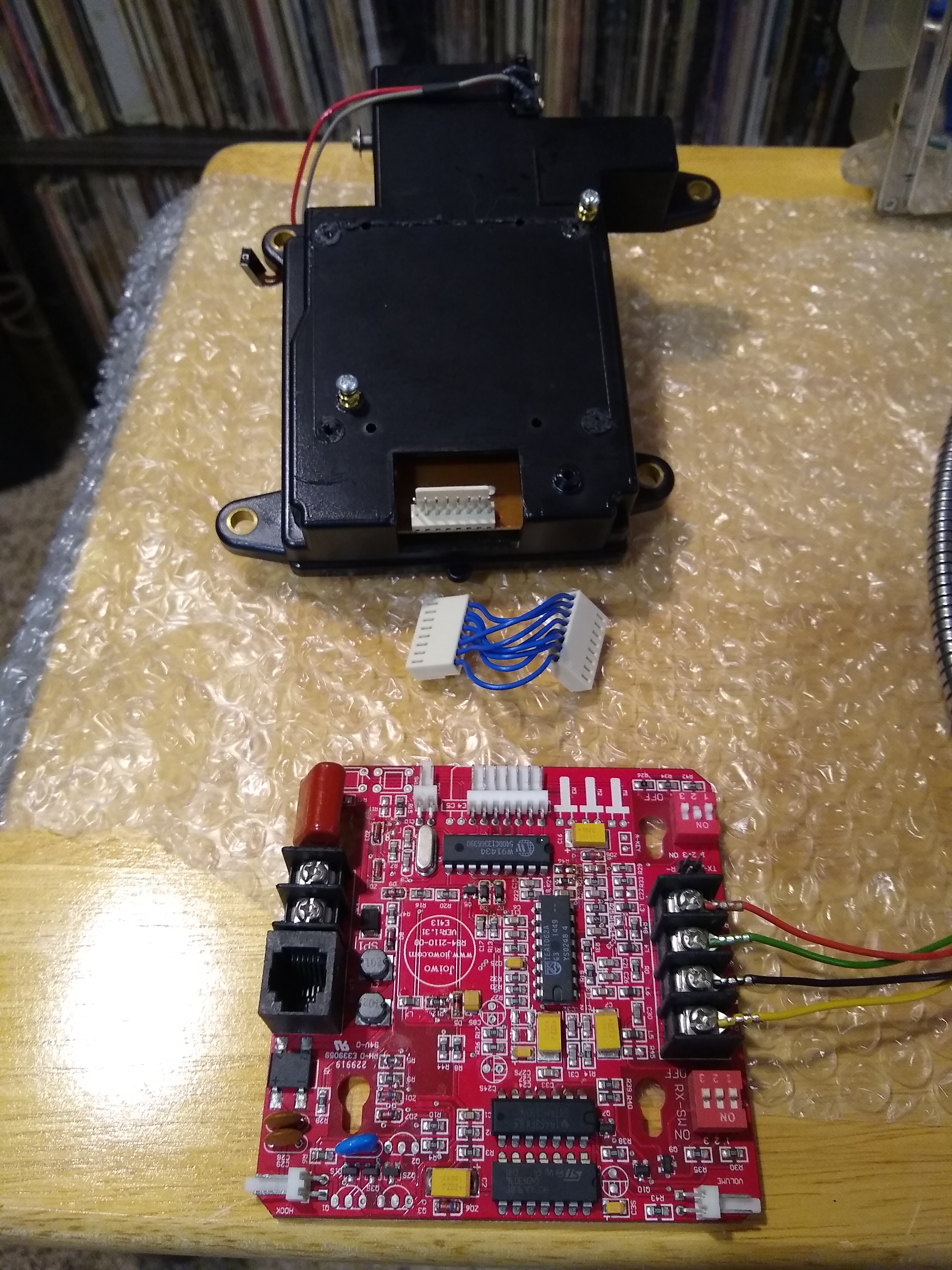
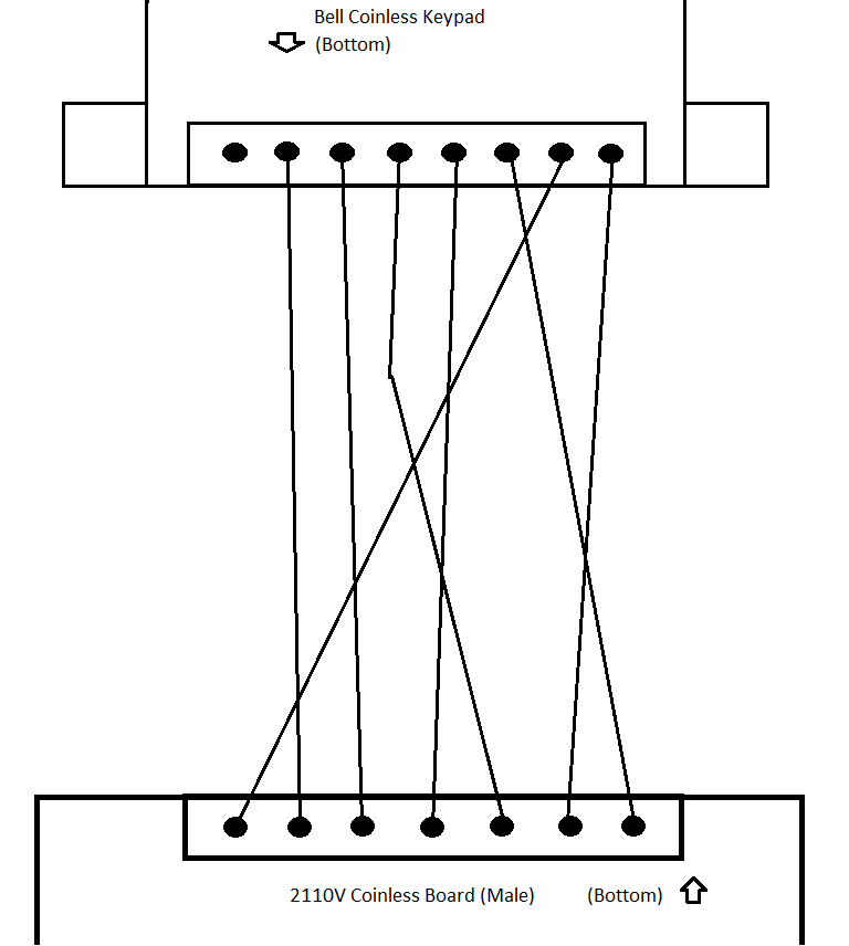
Next, I noticed that the connection between the Coinless keypad and the 2110V board was not as simple as directly wiring each pin together in sequence, there was a jumper where pins were crossed over one another to get the proper signals from the keypad to the board. So, even though I was able to determine the pinout for both the Coinless and Protel keypads, they wouldn’t be much use without knowing how this jumper was wired. I was able to easily trace these wires and diagram them as well, showing how the Coinless kaypad connects with the 2110V.
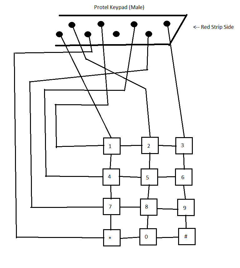
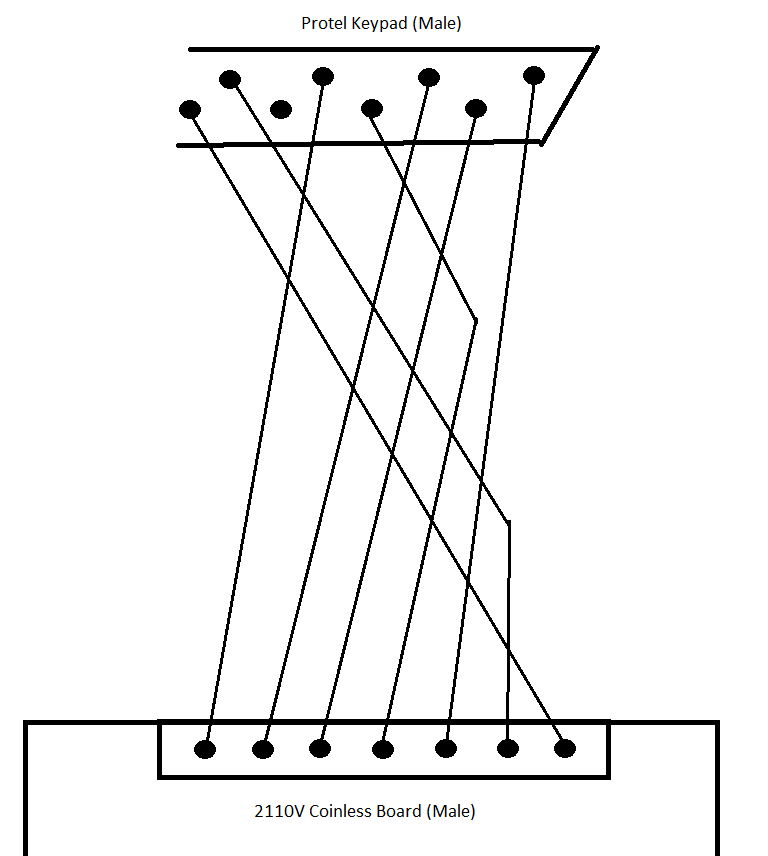
From here, it was trivial to create a final diagram showing how the Protel keypad could be directly wired to the 2110V board by comparing the Protel pinout to that of the Coinless keypad, and then tracing those connections through the jumper.
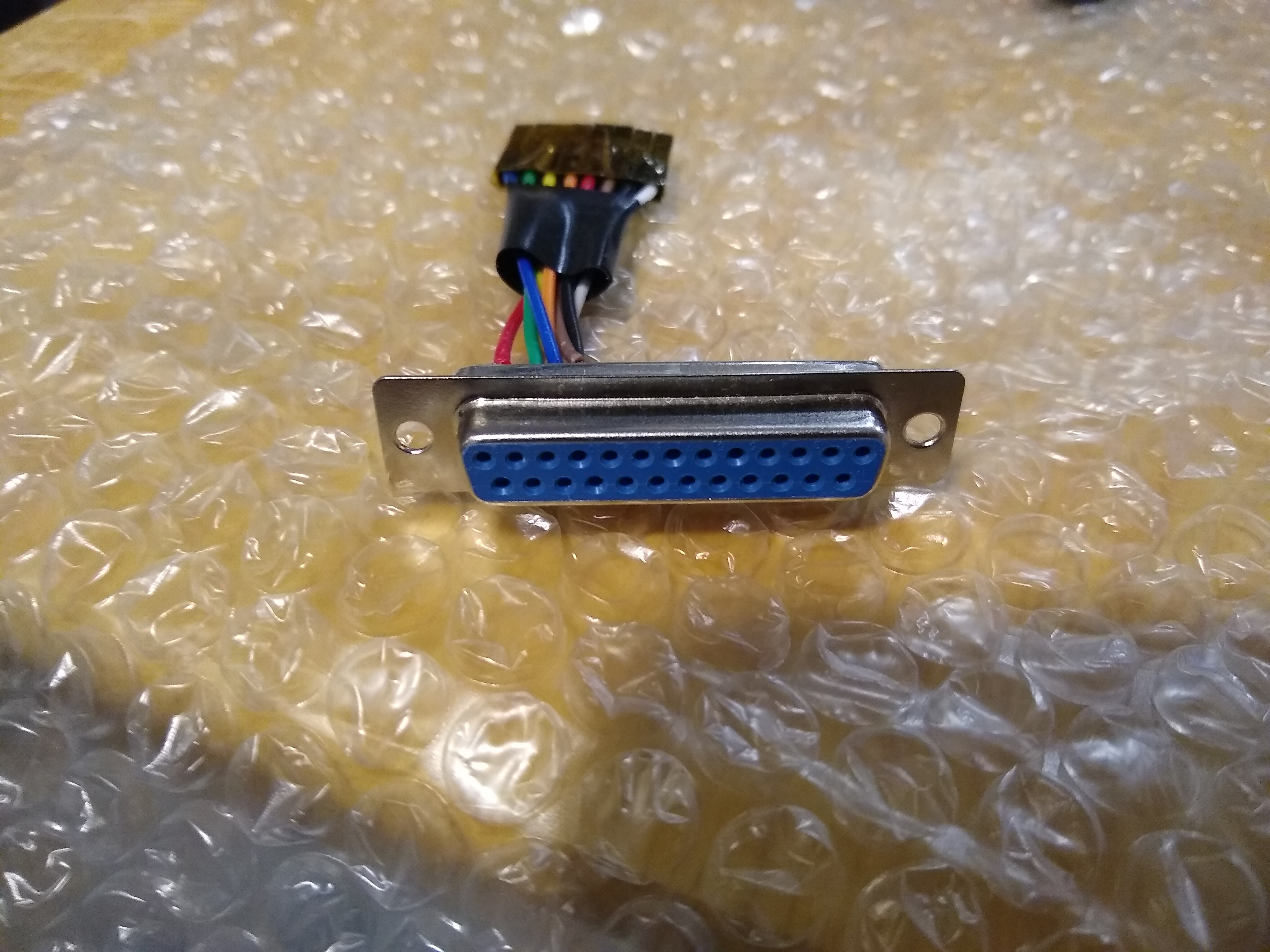
I was able use this diagram to create an adapter with a DB-25 socket and some Dupont female jumper wires to connect the Protel keypad to the 2110V directly.
In the future I hope to explore other keypads to determine their pinouts so they can be used with the 2110V board, or for any project needing a keypad.