Fixing a Protel Payphone Part 3: Modem Repair
This post is a continuation in a series, “Fixing a Protel Payphone.” To view the previous installment, check out Fixing a Protel Payphone Part 2: Installing ExpressNet
The next step to getting XNet running was connecting up the modem. Protel actually produced their own modem, the UPMS 1200, which was designed specifically to program payphones via XNet. Many people online stated that in order to program my 7000-series board, I would absolutely need the UPMS modem and nothing else would do. But wait, I thought, wouldn’t a standard Hayes-compatible modem work instead? XNet even has options for a generic-non-protel modem so surely I could find an alternative. I became further confused when people told me only the 7000-series boards needed the UPMS modem and other boards worked just fine with something more readily-available.
I’ve later learned that 7000-series boards don’t exactly require the UPMS modem (though for the sake of our setup they sort of do, but I’ll need to address that in another post), but I can now understand where the confusion on this came from. A Protel 7000 series board has a built-in modem that supports a 1200 baud connection, but unlike most modems which will use FSK modulation at 1200 baud (Bell 202), Protel boards use PSK modulation which makes them incompatible. Somehow, this morphed into the myth that the 7000-series boards could only be programmed at 1200 baud when in-fact they can also be programmed at 300 baud (standard Bell 102) if the software is configured to use a non-Protel modem.
At the time though, I didn’t know this. Lucky for me though, right around the time I was trying to determine what modem I could use I was informed a UPMS 1200 had just listed on eBay. I figured best case scenario I would be able to use the UPMS to make sure that my setup worked and then experiment from that point to show definitively whether other modems would or wouldn’t work. Worst case scenario I still had all of the “proper” components for a functioning setup and it would just come down to determining proper configuration and avoiding human error.
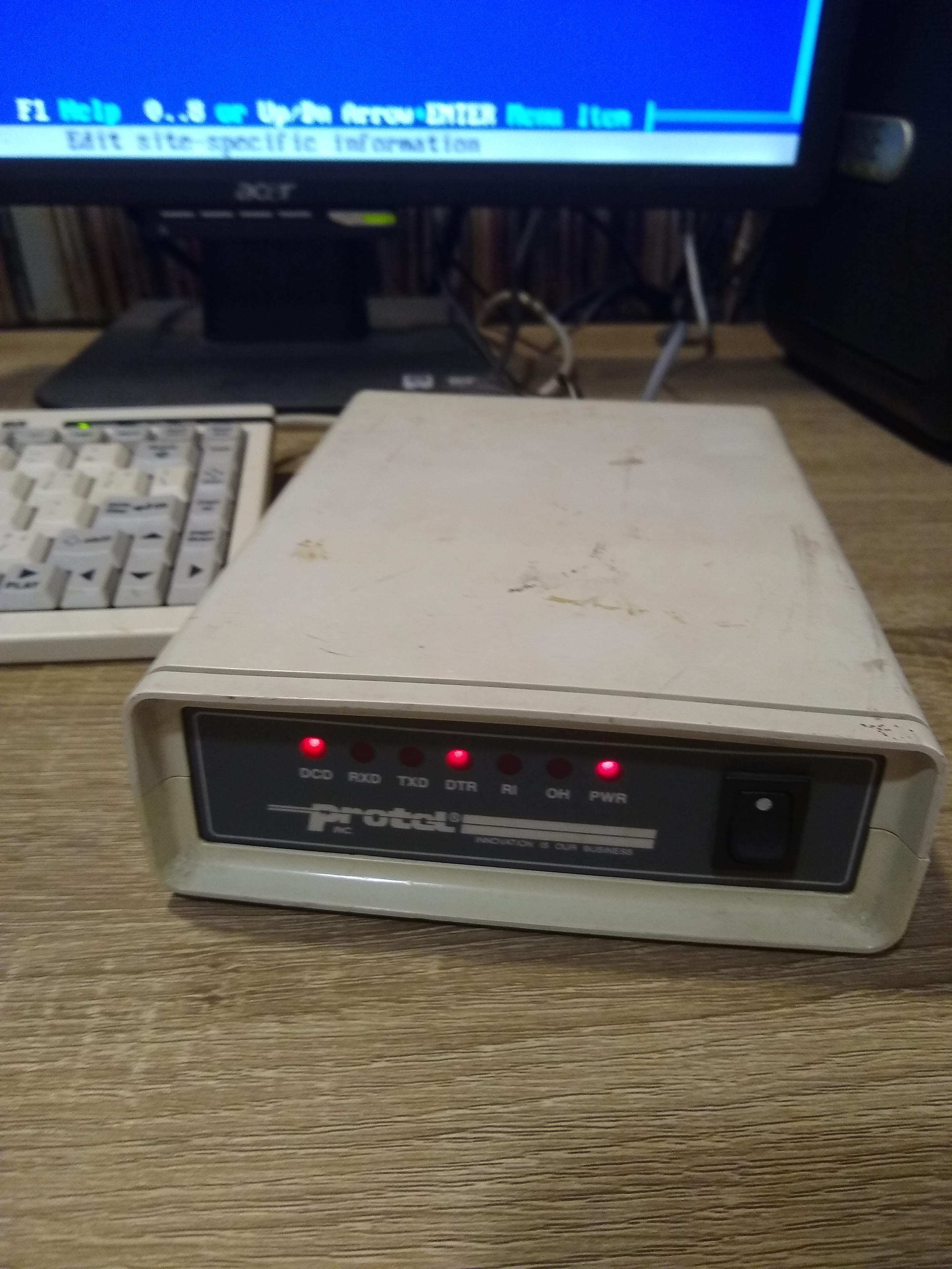
Upon receiving the UPMS modem, I hooked up the phone line, wired the data port to the serial port on the thin client, and powered it up. Immediately I head a loud pop from the internal modem speaker and then a loud dial-tone. It seemed like the modem immediately went off-hook without being configured to do so. This wasn’t a good sign. Starting XNet sends some initialization configuration to the modem so I loaded it up and watched it open communication and send the init string. The modem still wouldn’t give up the loud dial-tone.
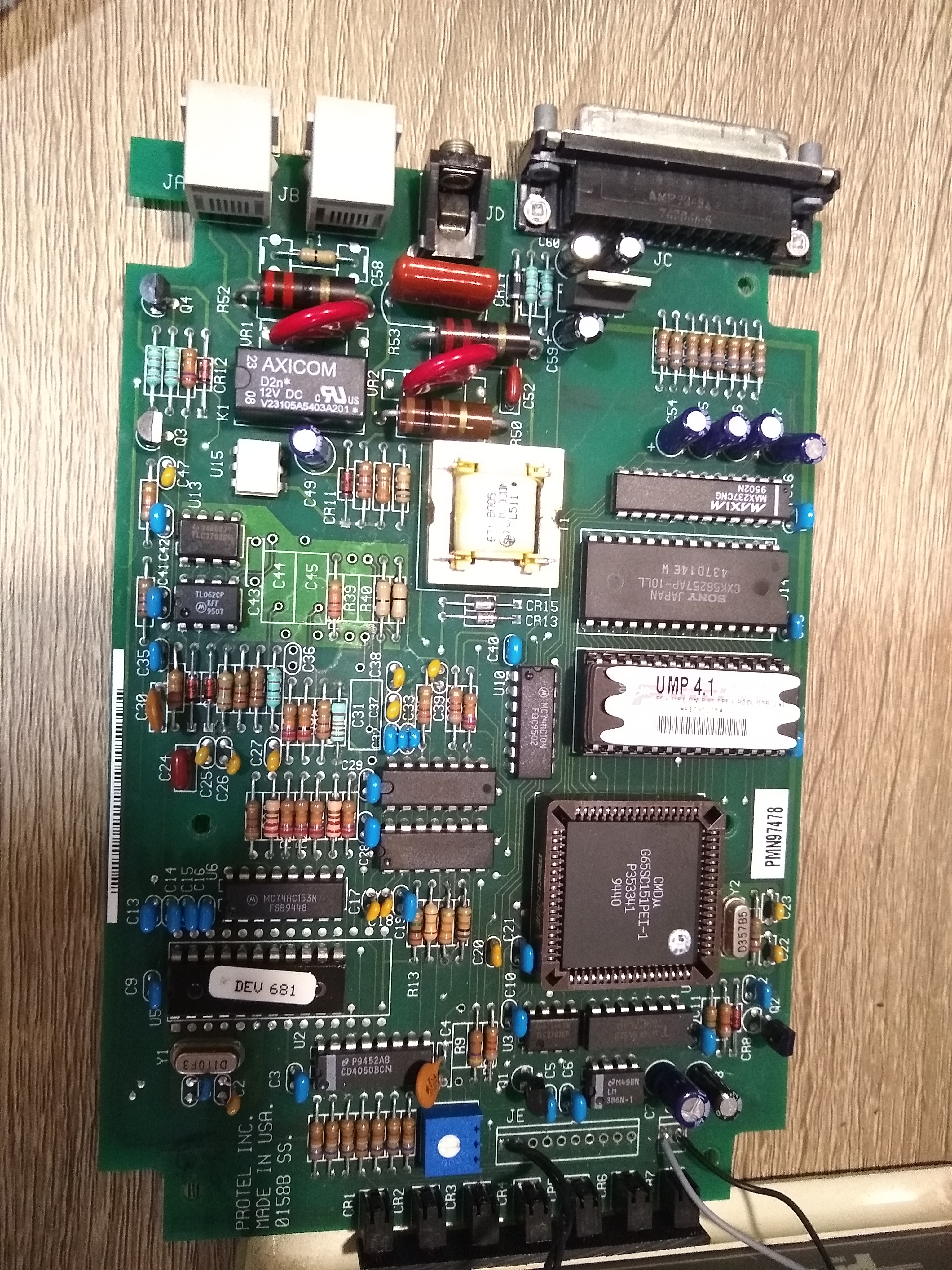
At this point I knew that the modem was broken, so I decided to open it up and investigate for any failures. Cosmetically, the inside of the unit looked just fine and all of the components seemed to be intact. I noticed that the board had a handful of electrolytic capacitors so I recorded the values of these and ordered replacements. Even without the issue I was facing, replacing these capacitors would have been on the to-do list considering the age of the modem and the fact that I would want it to be running 24/7.
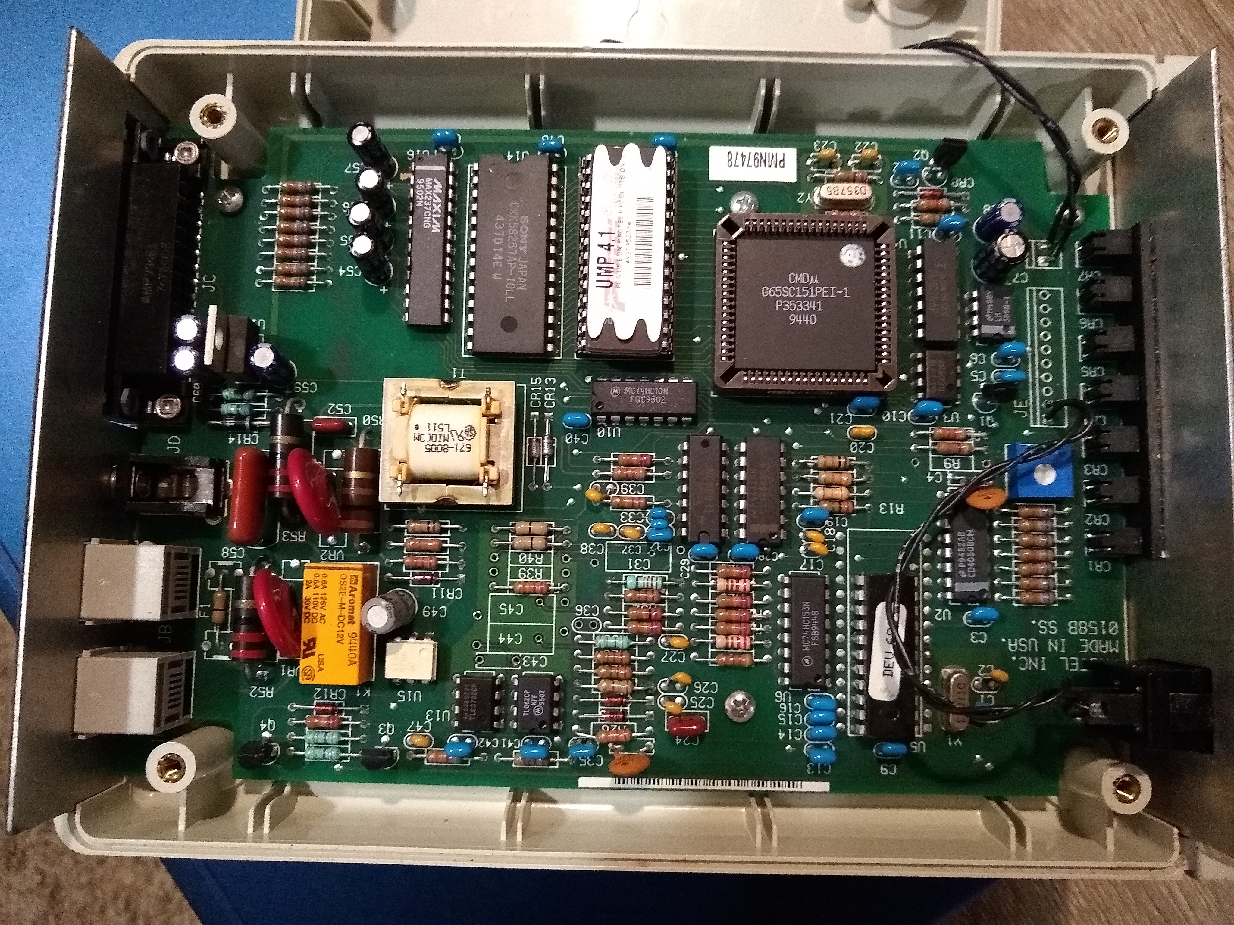
For anyone else attempting this, the capacitors needed are:
- 1x 100uF 25V Aluminum Cap
- 4x 22uF 50V Aluminum Cap
- 1x 10uF 63V Aluminum Cap
- 4x 10uF 50V Aluminum Cap
This was only a few dollars worth of parts and luckily all of the capacitors are through-hole so replacement wouldn’t be too difficult.
When the capacitors arrived I went ahead and replaced each one on the board one-by-one with a soldering iron, desoldering vacuum tool, and solder wick over the course of 20 minutes.
After replacing the caps, I wired the modem back up to the thin client and telephone line and then turned it on. No loud dial tone! Further, XNet reset and initialized the modem as expected. For a quick test the modem was plugged into an ATA connected to my PBX. I used a phone also connected to the PBX to dial the extension corresponding to the modem and the modem happily answered the call!
Later on, I noticed a lingering issue where it seemed like sometimes the modem didn’t hang up right away. I was told this could be related to a worn-out “sticky” relay in the modem which could be replaced. Further, I noticed that when the modem wasn’t in use I could still hear a faint fast-busy signal coming from the internal speaker along with a fairly loud burst of modem chirping for a few seconds whenever an incoming call was answered.
I decided to replace the relay and ordered the following component:
I also dug up a small SPST switch from my parts drawer to use as a toggle for the modem’s speaker. Unfortunately, it didn’t look like a software solution would work to mute it as I tried appending both &M0 and &L0 to the init string with no success.
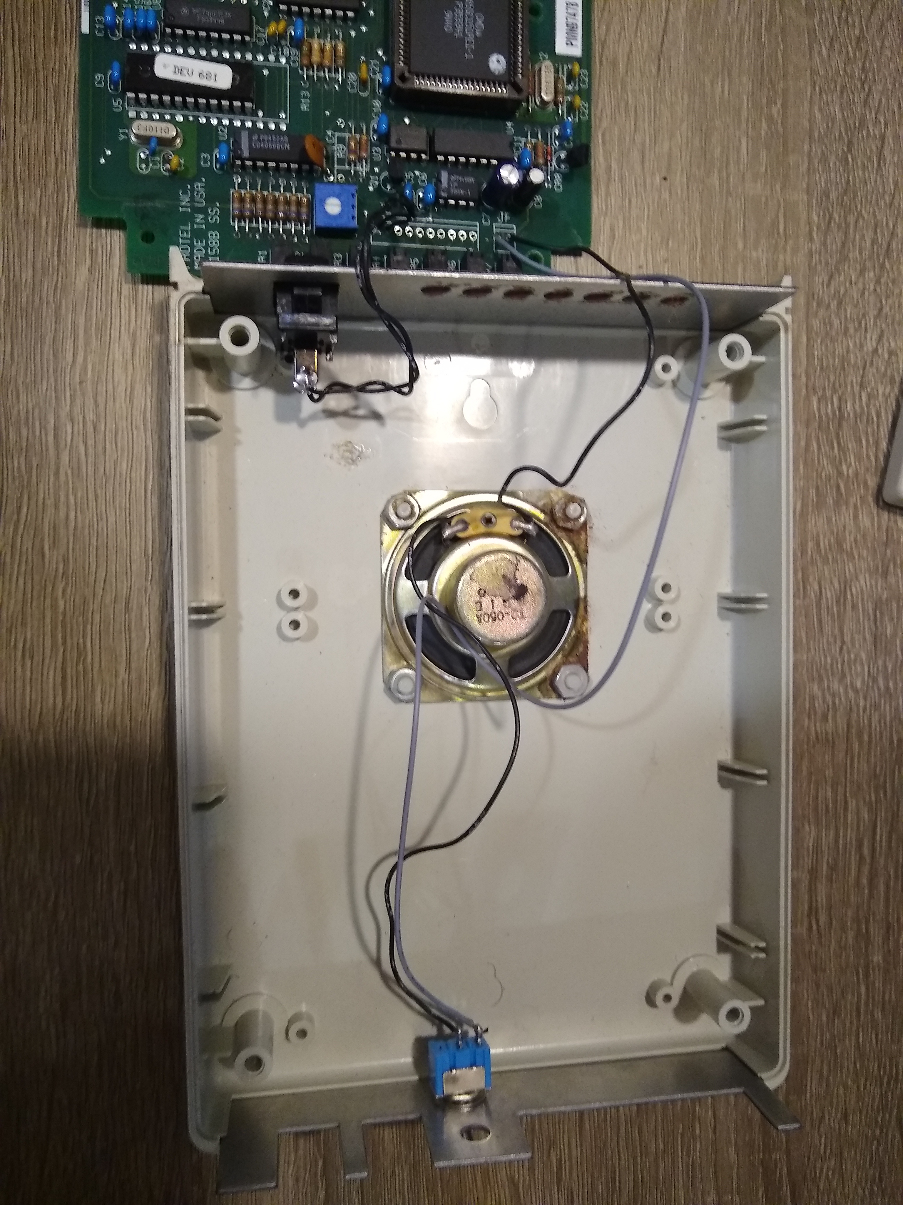
The existing relay was desoldered and replaced in the same process as the capacitors previously were. For the toggle switch, I first mapped out a location to install it on the modem’s back panel below the power hack. Using a marker to note where I wanted the switch, a punch to get an initial guide divet, and a series of drill bits working up to 1/4”, I was able to drill an appropriately sized hole to panel mount the switch and then fasten it in place. Wiring the switch was done by disconnecting one of the speaker leads from the modem’s board and wiring it right to the switch while the second contact of the switch was wired to that now-empty point on the board with a small length of wire.
A video documenting this whole process is available below. Luckily it all worked great first try!
With the components replaced in the modem, it should hopefully be able to operate for many years to come. With the new switch, I can operate the modem silently so it doesn’t create any annoying audio while operating.